Valve positioners positioner pneumatic valves actuators principles cutaway Valve symbols control symbol flow instrumentation pressure common used engineering valves diagrams diagram drawings instrument developing piping drawing iso instrumentationtoolbox Pressure compensated non valves flow control hydraulic schematic needle diagram troubleshooting
Flow Control Valves - Hydraulic Symbology 204
Valves pneumatic
Types of valves
Flow control valve circuit diagramControl valve parts name || basic knowledge of control valve parts in Compensated valves temperature increased explain velocity henceFlow control valve.
Valve positionersValves types valve globe control flow schematic open close wide rate operation use Flow control valvesFlow control valves hydraulic symbology 204, 55% off.

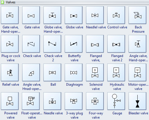
Valve symbols valves flow process diagram symbol gate instrumentation control piping engineering boiler pump mechanical plumbing standard drawing their pfd
[diagram] hydraulic flow control valve diagramValves actuator instrumentation instrumentationtools functions principle working device breather Control valves flow hydraulic work animation valve diagram system mechanical wiringControl valve symbols.
Valve flow pressure control compensated diagram work does fluid path components simplified pressures illustrating within click enlargePressure compensated flow regulator valves • related fluid power Proportional hydraulic flow control valveFlow control valve hydraulic symbol pressure compensated diagram parker valves system way 31a hannifin reprinted corp permission partial figure.

Needle valve symbol
How flow control valves workPrinciple engineeringlearn Valve directional control partPiping design tips and guide : process flow diagram symbols.
Simplified hydraulic circuit schematic for the motor efficiency testHow does a pressure-compensated flow control valve work? Directional control valve basicsCheck valve symbol.

Hydraulic flow control valves
Non-pressure-compensated valvesCommon p&id symbols used in developing instrumentation diagrams Control fluid power systems discrete symbols schematic system diagram components represent pumps electronicFlow control valve: definition, types, components & working principle.
Circuit motor simplified piston efficiency valve directional[diagram] bobcat control valve diagram Valve flow control hydraulic diagram pressure compensated parker operation valves bobcat two 31b permission reprinted hannifin showing figure auxiliary dcvHydraulic flow control valves.

Schematic diagram of flow/pressure valve control: (a) meter-out flow
Pressure-compensated valvesValves understand controls fluid fluidpowerjournal Schematic diagram of the flow control valveValve schematic.
Flow control valves[diagram] hydraulic flow control valve diagram Hydraulic symbols flow control valve at jae gil blogValve pneumatic sectional analysis electronics vibration fault detection.
Mechanical valves: a device for control flow and pressure
Pressure flow compensated regulator valves valve control circuit hydraulicFlow control valve Pressure compensated schematic flow control hydraulic valves valve diagram orifice troubleshooting figFluid power systems.
Control valves components types valve parts name working basic itsValve flow control .


![[DIAGRAM] Hydraulic Flow Control Valve Diagram - MYDIAGRAM.ONLINE](https://i2.wp.com/www.manufacturinget.org/wp-content/uploads/2012/09/circuit-3.png)

